Loading
early Bourdon
brass, copper, glass, silvered brass, steel
This Bourdon pressure gauge, dating to around 1855, belongs to the very earliest period of the practical adoption of pressure gauges. The instrument is not only a technical artefact but also a clear material expression of the transition from liquid-based methods of pressure measurement to compact metallic systems that laid the foundation for the entire subsequent history of mechanical pressure gauges.
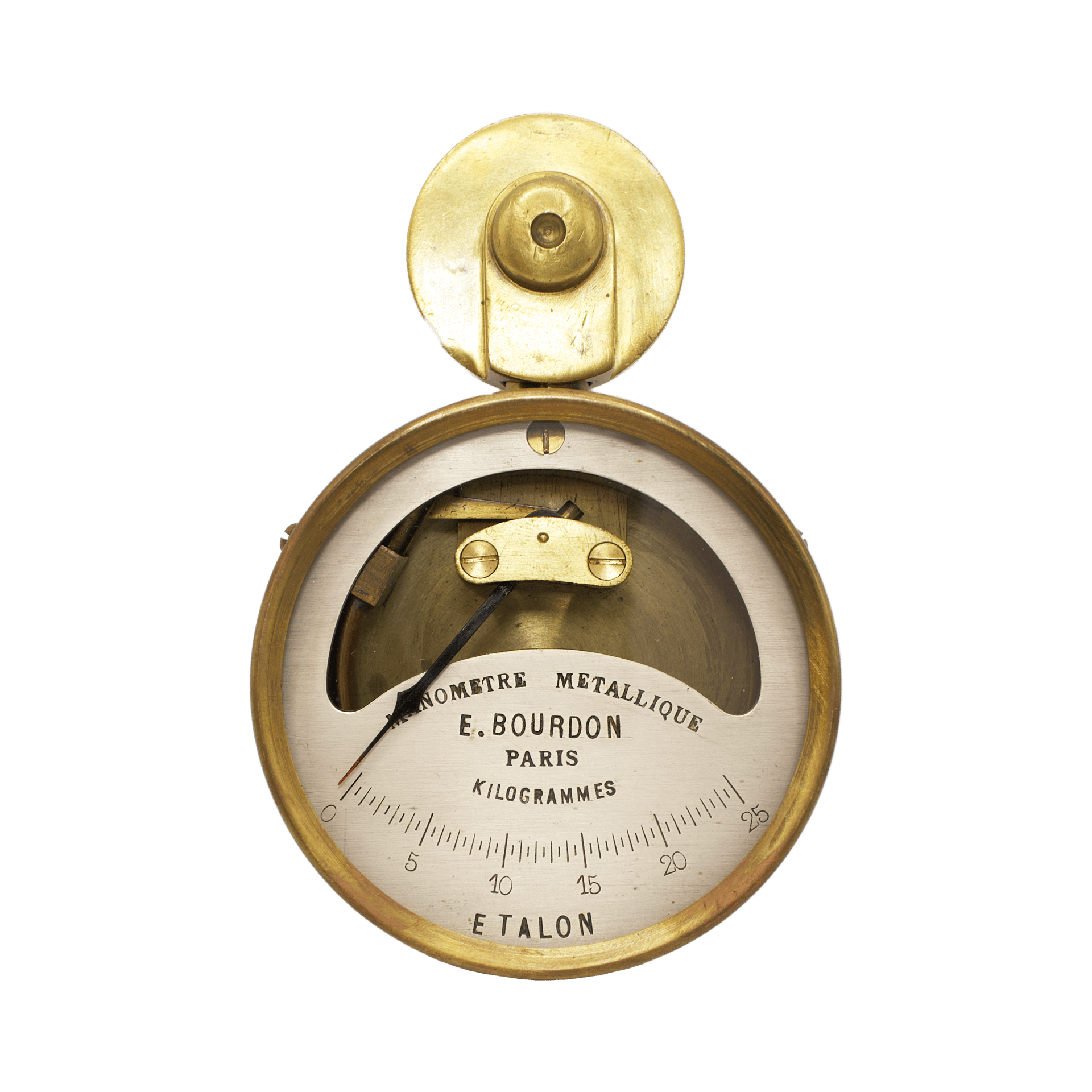
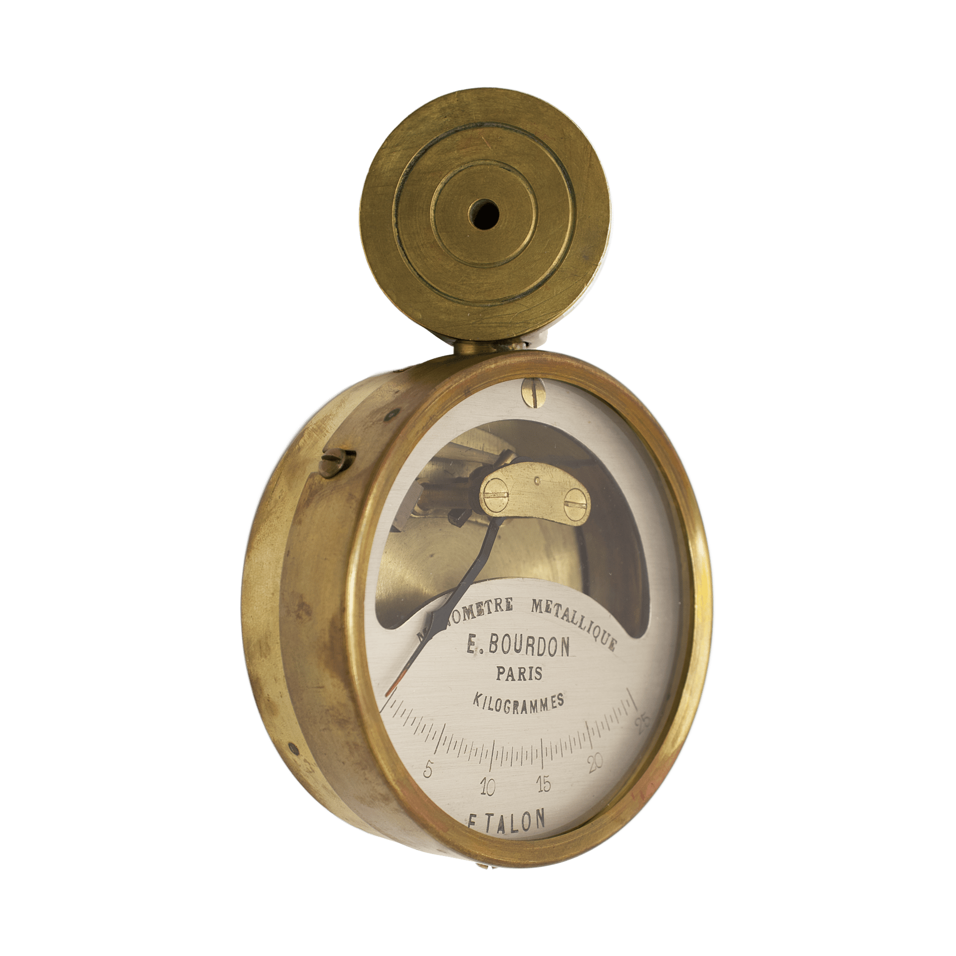
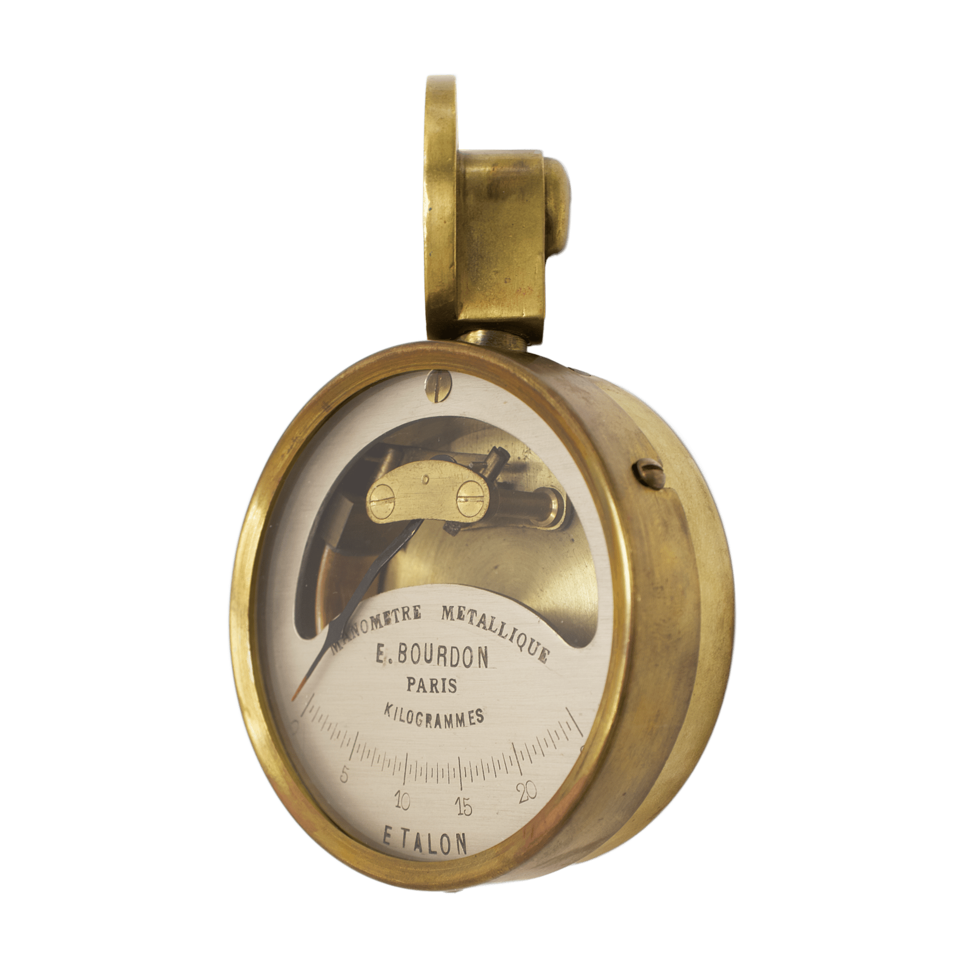
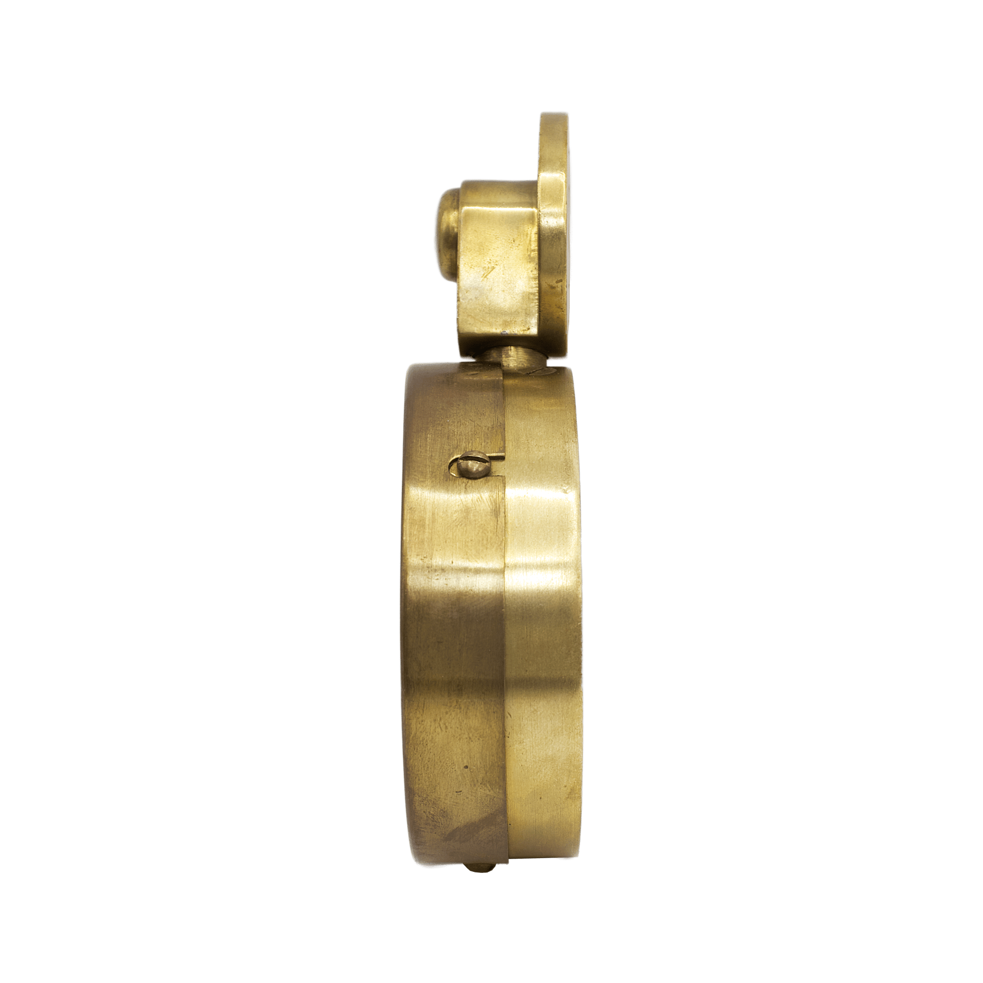
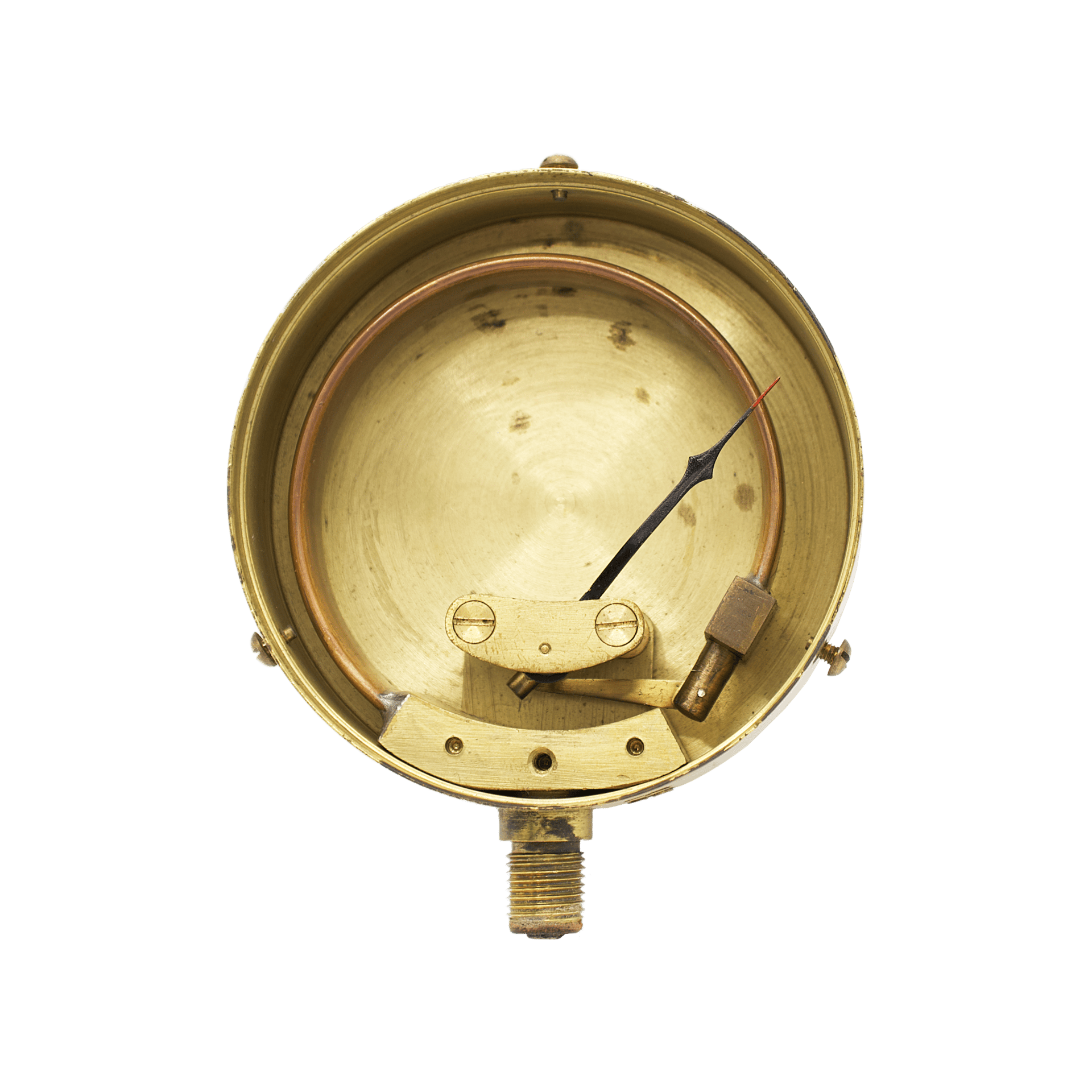
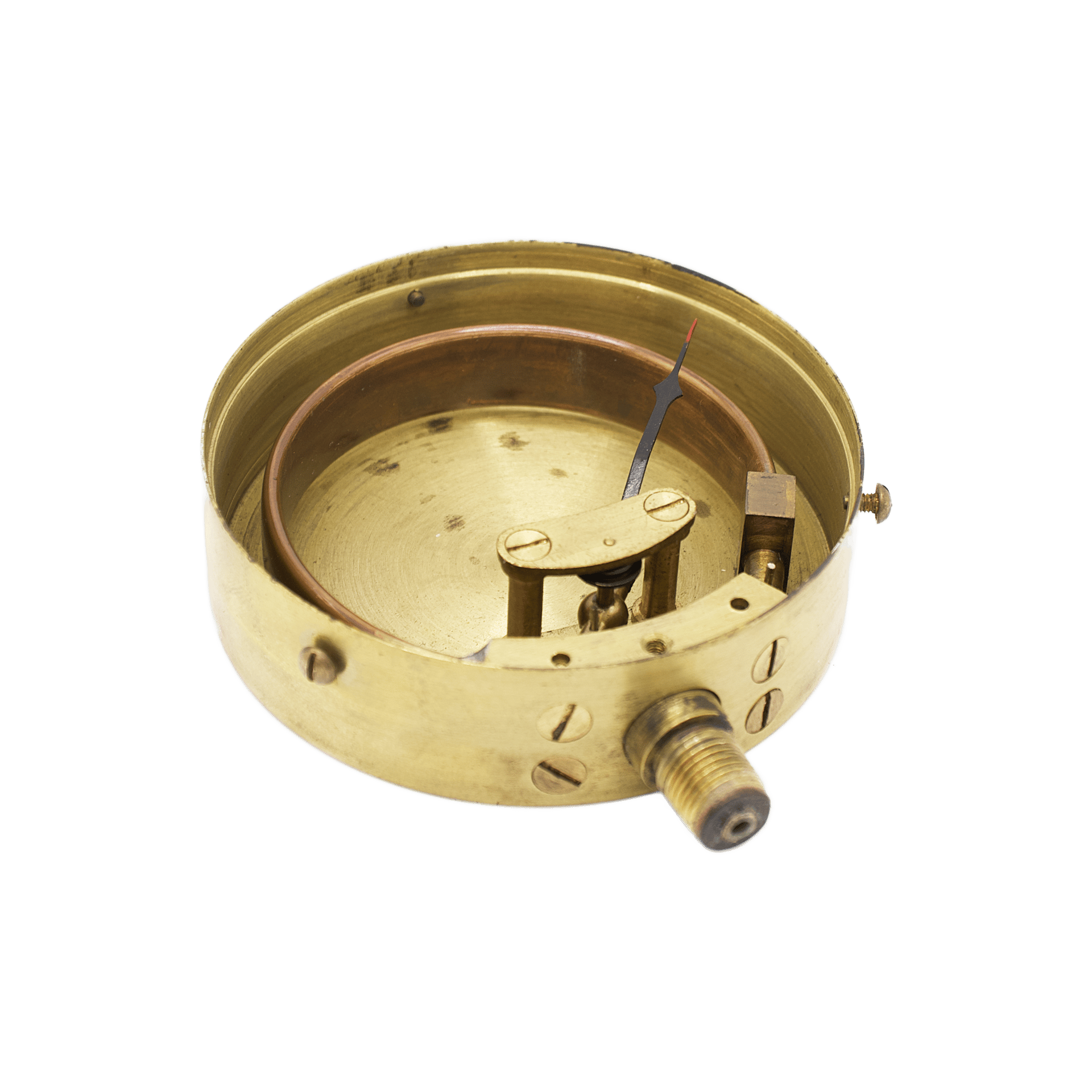
The gauge is housed in a compact circular brass case, turned on a lathe and assembled from several carefully fitted components. The upper part of the case is fitted with a substantial, screw-on inlet adapter—a brass disc with a central aperture designed for connection to the pressure source. The concentric circular grooves clearly visible on the surface of this element serve functions of self-centering and seating stabilization, as well as sealing. In the period before the widespread use of standardized rubber O-rings, the tightness of pressure-gauge connections relied on a combination of precise metal-to-metal fitting, soft gaskets (leather, fibre, lead, and later vulcanized rubber), and relief grooves. These concentric channels provide spaces into which the gasket material can partially flow during tightening, distributing itself evenly across the contact surface. As a result, contact pressure is not concentrated at a single edge but spread over a ring, significantly reducing the risk of air ingress or pressure leakage. The grooves also act as a barrier against creeping leaks: if pressure attempts to force its way through the joint, it must follow a labyrinthine path interrupted by the circular recesses. This principle was well known in nineteenth-century steam and hydraulic fittings and was widely employed long before the advent of standardized sealing elements.
The front of the case is closed by a thin brass bezel, secured to the body by three evenly spaced screws. The bezel retains a flat mineral glass, protecting the dial without introducing distortion or glare. Its design is deliberately restrained and purely functional, entirely subordinated to maintaining compactness and legibility.
The dial is made from a thick plate of silvered brass. In its upper portion, a large arcuate cut-out reveals the working element of the instrument—the famous Bourdon tube. The scale is engraved directly into the metal and calibrated in kilogrammes, over a range from 0 to 25, a characteristic feature of high-range gauges intended for steam and hydraulic applications. In this context, “kilogrammes” denotes kilogram-force per square centimetre, a unit of pressure widely used in mid-nineteenth-century engineering and steam technology. The term kilogrammes functioned as professional shorthand, read as “kilograms of pressure,” that is, kilogram-force per square centimetre, without the explicit “per cm²”, which was considered self-evident. The graduations are executed with high precision and at uniform intervals.
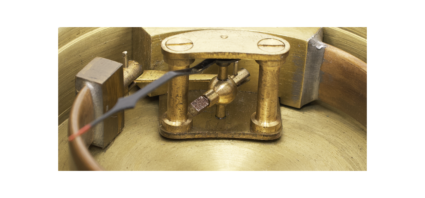
Inside the case, the Bourdon tube is an elastic metallic element of almost circular form, bent into an open ring and made with an oval, flattened cross-section. This shape is fundamental to its operation: under internal pressure, the tube does not merely expand, but tends to change its geometry, adopting a more circular cross-section while simultaneously reducing the overall curvature of the arc. One end of the tube is rigidly fixed within the case and connected to the inlet fitting through which the measured medium enters, while the other end is hermetically sealed and left free. As pressure inside the tube increases, this free end moves outward; the displacement is highly reproducible and proportional to the applied pressure.
The motion of the free end of the tube is transmitted to a small linkage connected to it by a pivot. This joint ensures that even minute movements do not generate parasitic stresses or disturb the linearity of the mechanism. The force is then passed to a lever system whose purpose is to convert the small, awkwardly directed motion of the tube into a movement suitable for driving the indicating mechanism. At this stage, mechanical amplification occurs, allowing an extremely sensitive but low-displacement element to function as a practical measuring sensor. The linkage rotates a lever through whose centre passes the pointer axis, held at the top by a brass bridge. Mounted on this axis is the blued-steel indicating hand, which points to the values on the dial and is distinguished by a red-painted tip.
Via the threaded fitting, the instrument is connected to the system being measured—a steam boiler, compressor, hydraulic line, or gas conduit. The pressure of the medium directly fills the internal volume of the Bourdon tube. As the pressure rises, the tube tends to straighten, its free end shifts, and the entire kinematic chain is set in motion, culminating in the rotation of the pointer across the scale. When the pressure decreases, the elasticity of the metal returns the tube to its original state, the mechanism operates in reverse, and the pointer smoothly returns. The absence of springs in the conventional sense, minimal friction, and the simplicity of the construction ensure high reliability and long service life.
Such pressure gauges were intended to measure gauge pressure, that is, pressure relative to atmospheric pressure. In the nineteenth and early twentieth centuries, they were used to monitor steam pressure in boilers and engines, compressed air in compressor installations, water and oil in hydraulic systems, and various gases in industrial applications. In the case of instruments marked étalon, this designation indicates calibrated reference gauges, used for the verification and adjustment of other measuring devices.